
How to Meet the Differing Objectives of the End User and System Designer
This presentation/paper was given at the American Filtration and Separation Society (AFS) 2017 Fall Conference, September 18 – 20, 2017, sponsored by the American Filtration and Separations Society.
Author: David Pearson* BA (Oxon), Managing Partner, Membrane Specialists LLC
Lewis Pain B Sc, Managing Partner, Membrane Specialists LLC
2 Rowe Court, Hamilton, OH 45015
Abstract
The end user and potential membrane filtration system designer and supplier often have both conflicting and mutual objectives when undertaking a pilot test of a membrane system. The end user will want to ensure that a suitable product can be reliably and consistently manufactured and may want to produce product for quality control and market testing. The system supplier will want to ensure that data on the key parameters involved in designing a membrane system have been adequately captured to enable a design to be completed. Both parties will want to be confident that if a membrane filtration process is installed at a commercial level, there will be no significant and unwanted surprises, with the membrane system meeting both capacity and separation objectives.
Thus establishing, prior to testing starting, an agreement as to what each party’s technical and commercial expectations are and how these are to be addressed and explored during piloting is critical to the success of the testing program.
Using experiences gained with multiple membrane filtration pilot testing programs, the various key issues will be presented. Topics will include how to select the right membrane filtration configuration, what process variables need to be explored, what scale of full-scale and pilot testing might be needed and how risks are identified during piloting so that these can be minimized prior to a project moving forward.
Introduction
The performance of membrane filtration separation systems is well understood for brackish and sea water applications with some membrane manufacturers providing free internet downloadable design models to enable, in particular, Reverse Osmosis and Ultrafiltration systems on water to be configured.
Some process applications are also standardized with substantial public domain information from many years of research and development work by industry and academia. Perhaps best resourced are membrane applications in the dairy industry, although process limits continue to be challenged and expanded.
Published data sufficient for a proper design is unlikely to be available and the process ideas being investigated may be unique, novel or confidential.However when companies are developing new products where the use of membrane separation technology is being
considered, or if they are looking at treatment and possible recovery of product or water from wastewater streams, to establish a membrane process design will often required pilot testing. This will allow the end user to evaluate if the separations they are seeking can be achieved and enable a potential membrane system supplier to capture enough data for an informative and low risk process design to be costed.
The development process is likely to involve significant costs for both the membrane system designer and end user, who at times may be the same company. By establishing clear expectations, goals and pass/fail gates early on will save both parties considerable sums of money and/or wasted time of valuable personnel resources and make the pathway to a final design more efficient and the outcome more likely to be successful.
Membrane System Design: Standardized Processes
- Water RO
- Water UF
- Dairy RO (Cheese Whey)
- Dairy NF (Desalting)
- Dairy UF (Whey Protein Concentrate)
- Juice Clarification (Apple Juice but with care)
Membrane System Design: New and Novel Processes
Issues and Challenges:
- Confidentiality
- Lack of Published Data
- Unique Process Streams
The Decision Making Process
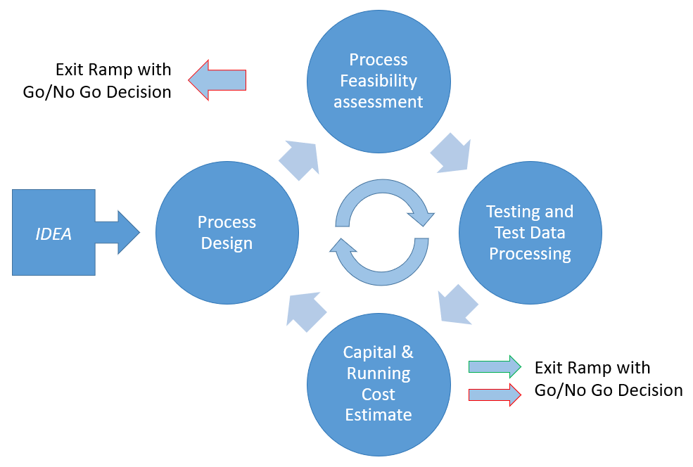
Figure 1 The Decision Making Loop
Let us take a hypothetical example of how the development of a membrane process starts.
The End User (EU) has a separation need and somebody in the end user company has an IDEA that membrane separations might offer the possibility of achieving the separation objective but does not know how to go about finding out if it can work or what the solution would cost.
The first step might be some Internet Searching but there is little information available for what is a new application with no public domain data available. The EU person then contacts an “expert” in the field who might be a consultant or Membrane System Designer and Supplier (MSDS). Let us assume the latter.
Now begins an iterative loop of design, costing, testing and evaluation as detailed in Figure 1 below. There is a conversation with the MSDS who determines that there is a possibility of the separation process working. The parties resist launching into pilot testing immediately, but the MSDS comes up with a conceptual design making decisions about membrane configuration, flux and separation to produce a rough capital and running cost estimate.
At this point the first Go/No Go decision point is reached with neither party having yet done any testing. The EU has to make a decision as to whether the membrane process, if it did work, is economically viable. A decision may be made there and then not to proceed, however if the parties consider there is a realistic chance of achieving the separation required at an economical enough cost, they continue around the loop moving to the first testing phase.
The EU and MSDS need now to act as a team working closely to ensure that each party obtains enough information from the testing and subsequent evaluation to move onto the next decision point, where it may be determined from the data obtained that the development process should be curtailed.
If the results are acceptable then a revised design is made and costed to reach the Go/No Go decision point again. Assuming the costing is still acceptable more detailed testing will start until after enough turns around the loop a decision to move forward can be made.
The collaboration between the MSDS and EU will need to look at the factors that affect the choice of membrane and membrane configuration. There are a number of key decisions, which are not irrevocable, to be made early in the development cycle. Some of these key decisions may have been already made during the initial feasibility and budget assessment. These Key Decision Points will be reviewed at each major review to ensure that the development process continues to move in the right direction and informed decisions can be made before committing additional resources to the project.
At this point the goals of the two parties to some extent diverge. A test protocol needs to be drawn up which clearly states the objectives of the trial, what tests are conducted, what resources are needed, what samples are to be taken and what analysis is to be made. The protocol may include what is considered a pass mark that is designed to avoid later disappointment or conflict between the parties and to ensure sufficient data is captured for the next key review. It is therefore appropriate to look at the key objectives of each party in the testing phase so that both parties understand the reasons for each other’s needs.
| Key Decision Points | Factors Affecting Decision | Timing |
|---|---|---|
| Membrane Configuration to be used: Spiral Hollow Fiber Spiral Polymeric Tubular Ceramic/Stainless Steel Sheer Enhancing | Presence of suspended Solids Nature of suspended solids Abrasion Process Temperature pH Presence of fiber Presence of non-aqueous solvents | MSDS Conceptual Design After initial testing |
| Final Concentration to be reached/Recovery | Viscosity Impact of Shear Osmotic Pressure Suspended Solids Precipitating Salts | Early with possible goal change after testing |
| Desired Permeate or Retentate Quality | RO/NF/UF/MF/Hybrid | Early with possible goal change after testing |
| Membrane(s) and membrane material to be tested | Resistance of membrane to feed fluid conditions Resistance of membrane to fouling Membrane Cleaning Chemicals Needed Resistance to Abrasion | MSDS Conceptual Design Early Testing |
| What to do with the non target stream - Retentate or Permeate | Disposal Options and Costs Reuse Options and benefits | Early in Process Samples may be needed to confirm choice |
Typical Key Objectives – End User
Typical key objectives will center on the quality of the product, generating a need to produce samples early in the development process. In the case of new product development these samples will usually be needed to sell the benefits to potential customers or to ensure the product is meeting internal quality goals. In the case of a food product, these tests might involve taste, flavor and texture. Often the membrane process is only a part of a complete process and samples might be needed for testing the performance of downstream processes.
The use of membranes on wastewater treatment and possible recovery of product or water from wastewaters might be in the increase as water resources become more stretched. In the wastewater field, a third party appears on the scene, the Regulator. Regulations may define goals by law, but regulators such as the EPA, State agencies or the local municipal wastewater plant receiving factory wastes or both. For these representative samples are required to ensure treatment objectives are met, such as the level of suspended solids, Fats, Oils and Greases, Biological Oxygen Demand (BOD) or Chemical Oxygen Demand COD).
Membrane separation processes do not treat anything (other than membrane bioreactors MBR’s). They simply separate a single stream into two separate streams. End users are also going to want to know enough about the unwanted stream so that it can be converted to alternate products or safely and economically disposed of. This too may require sampling for regulators approving receipt of those wastewaters to municipal wastewater treatment plant, surface water discharge or perhaps simply disposal by tanker to landfill.
Ultimately the end user is going to want to know the value of the investment that must be made and the long term operational costs.
Key Objectives – End User
- Product Quality
- Samples
- Meeting Regulations if Wastewater
- Investment Costs
- Operating Costs
Typical Key Objectives – Membrane System Designer
The goals of the membrane system designer are a little simpler to define equally challenging to reach.
There are only a few variables that can be tested in a membrane separation process:
- Operating Transmembrane Pressure
- Operating Temperature
- Cross-Flow Velocity
- pH
Of these variables, temperature and pH may be non-negotiable and defined by the product itself.
From these variables the MSDS is needing to understand the effect on flux (flow rate of filtrate through the membrane per unit area) and what, if any, membrane fouling results from changes to these variables.
All membrane processes will concentrate something be it suspended solids by microfiltration or ultrafiltration, or dissolved proteins, sugars, acids or other organics with any of the four principle separation processes, RO, NF, UF or MF.
Establishing an effective and sustainable membrane cleaning regime is key to the long term success of a membrane system and often forms a substantial part of a piloting operation.
The ultimate goal for the MSDS is shared with the end user and that is to know the value of the investment that must be made and the long term operational costs.
Key Objectives – Membrane System Designer
- Flux VS Concentration
- Pressure
- Temperature
- Cross Flow Velocity
- pH
- Separation VS Concentration
- Samples
- Pressure
- Temperature
- Cross Flow
- pH
- Impact on Investment Costs
- Impace on Operating Costs
Membrane System Designs:
The test protocol is also affected by consideration of what the final membrane system design might look like. This decision are not irrevocable at the start of the development process but if there is a change, it might involve additional testing. The EU is going to want to know the ramifications of making such a decision change early in the process.
For each design, the test protocol will need to address how scale up issues are handled, particularly where full size membrane housings or modules are not used.
There are three basic designs of a membrane system. One or other of these designs may be the expected final system design but it may be impractical to test the scaled up concept at a pilot level.
Once Through Design
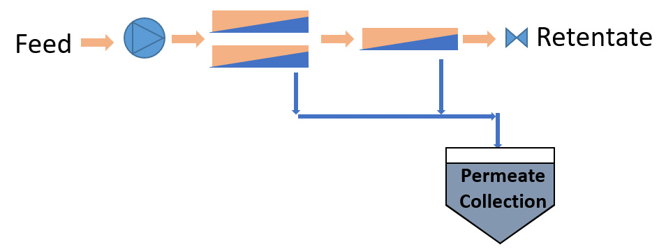
Figure 2 Once Through or Tapered Design
- Simple Pilot Testing Method
- Accurate Scale Up if Full Scal Modules/Vessels used
- Samples are representative of full scale if same taper arrangement is used.
- Length of Taper
- Use of Booster Pumps
- Pilot Plant may be large for sufficient feed flow for length of taper
This is typical of a water RO plant where feed is pumped into an array of spiral membrane vessels. The operating pressure is such that sufficient filtrate or permeate is produced in a single pass through the membrane array with the concentration of the retentate at the desired level.
Some of the first RO systems in cheese whey processing adopted the same design concept with tubular membranes. By placing sufficient modules in series, there was sufficient flux to enable a 6 or 7 module pass to double the concentration of the cheese whey.
Piloting this design is relatively simple. The permeate and retentate are both consistent with what would be seen on a scaled up design.
The client obtains their representative samples of permeate and retentate on a continual bases. The system designer gets their flux data and membrane cleaning and fouling are adequately investigated.
The challenge is that the pilot unit can become quite large as you need enough membrane area at the beginning of the array for the last pressure vessel in the array to still see sufficient flow into or out of it. It may not be practical to provide such a large pilot and the client may not be able to supply sufficient volume to the system.
Batch or Topped Batch Design
In this concept, feed is added to a batch tank and the feed stream circulated around the batch tank. Permeate is continually bled off so that the contents of the batch tank become more and more concentrated. Fresh material can be added to the batch tank during the process. At the end of the process run, a volume of permeate has been collected and there is the residual volume of concentrate or retentate left in the batch tank.
This process is typical of a juice clarification system where a large batch tank is continuously added to while clear clarified juice is captured for downstream bottling or evaporation.
The end user can obtain plenty of samples of representative product, whether the product is the permeate or retentate. The membrane system designer obtains valuable information with an infinite number of points on a flux concentration design curve. Membrane fouling and cleaning are easily investigated as the membranes are seeing at pilot scale exactly what they would see at full scale. Scale up issues are principally associated with tank sizes, batch volumes and batch residence times. Care must be taken in the design of the pilot test design to ensure that these parameters are close to expectations at a full scale.
This is the simplest membrane design to pilot, design and build. Tests are relatively easy to set up and operate at the pilot scale and the pilot plant itself is not complex. Feed volumes required will match the membrane area piloted. Scale up issues are primarily associated with whether or not a full scale membrane vessel or housing is being tested.
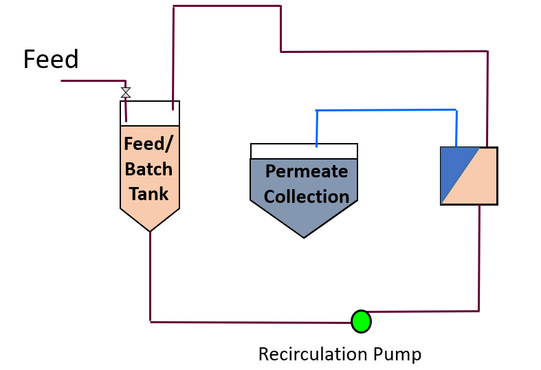
Figure 3 Batch or Topped Batch Design
- Simple Pilot Plant Design
- Simple Pilot Testing Method
- Accurate Scale Up if Full Scale Modules/Vessels used and tank size and volumes are proportionate
- Samples are representative of full scale and few samples needed
- Long hold-up time
- Retentate is not a continuous flow
- Permeate flow will vary with time
Continuous feed and bleed
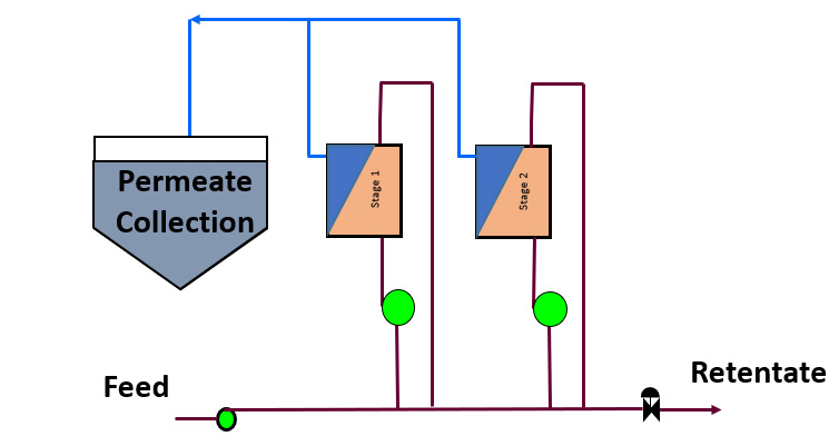
Figure 4 Continuous Feed and Bleed (Multistage Recycle) Design – MSR
- Complex Pilot Plant
- Simple Pilot Testing Method
- Accurate Scale Up if Full Scale Modules/Vessels used and number of stages the same
- May need to run at lower concentrations at each stage
- Short hold-up time
- Retnetate and permeate continuous and possible constant flow
- Permeate flow will vary with time
Many larger membrane systems, particularly in a process environment, work on a continuous feed and bleed basis. If the tapered design is not feasible because the recoveries cannot be achieved in a single pass, then a Multi-Stage Recycle (MSR) design, or continuous feed and bleed design similar to Figure 4 below may be required. There may be multiple stages. This design has the additional advantage that a stage might be isolated for cleaning or service without having to shut down the complete process.
This is the most difficult configuration to pilot unless you use a pilot unit with as many stages as the eventual scaled up system is designed with. Starting out, it is probable that the number of stages is not then definable.
The pilot is therefore very unlikely to mirror the scaled up design and a design model is going to be needed to predict the quality of the permeate and retentate, requiring more analytical work and time.
In such an arrangement each stage operates on a continual basis at a constant concentration depending on the flow rate of permeate from each stage. The system designer is now looking to generate performance data at the concentration of each stage. To do so would require that the final retentate from the pilot was not always at the final concentration of the product.
Permeate quality is also affected by the number of stages and passage of solutes at each concentration. To predict bulk permeate quality on a multi-stage design requires an understanding of what passage of solutes each stage is running at so that scale up design modeling can be done.
Membrane fouling may also depend on the concentration of retentate. Typically either the first stage, where fresh foulant arrives or the final stage, which sees the highest concentration, is likely to foul fastest. If one stage fouls then the concentration at which each stage is running may further vary, providing additional complication to a design model.
The end user therefore may never get a representative sample of concentrate or permeate as the mass passage of solutes into the permeate over a certain concentration factor will depend on the number of stages and the flux at which each stage operates. The membrane system designer will want to be able to run at a range of concentrations to develop both the flux/concentration curve as well as the concentration/passage curves to enable a more accurate design model to be created.
Testing Steps
The testing phase in the iterative loop described above in Figure 1 above might go through a number of different stages, each increasing in complexity and resource demands. These may be summarized, in Table 2.
The first test might be a very simple laboratory scale test on a single sheet tester or with a single hollow fiber membrane. Very small volumes can be used and an idea of whether or not a separation can be achieved. Flux data is unreliable, separation may not be accurate as the surface conditions probably will not relate to those seen on a larger scale module so although the cost of testing is low, the accuracy of a cost estimate derived from such a test is low. If the feed stream has the potential to foul the membrane this may materialize in these tests and some initial cleaning trials can be done.
At a similar cost, a volume of feed material might be sent to a test facility. Some MSDS’s have this testing capability as well as universities and research institutes. Larger sample sizes might be tested and larger membrane housings used in this type of test providing more reliable data. However the material being tested might have changed its nature in transportation and the flux and separation results might be affected. Where high volumetric concentration factors are being considered, large sample volumes may be needed as the final retentate volume will be small and the hold up volume of the pilot plant may become a limiting factor on the achievable concentration factors.
The work horse of piloting is clearly on site work where material is representative and variations in the feed water can be evaluated. This route is a good option where a membrane system is an add on or change to an existing process, but if the process is totally new, then feed material may not be available and pilot testing is limited to the scale of how the overall process is being developed. A discussion then around process risk and the scale of a membrane pilot is therefore appropriate, in case the overall process pilot capacity needs to be defined by the membrane step in that process. The scale of the pilot will reflect the volume of available material, the available space and whether or not this is the intended final testing step.
The ideal pilot to minimize process risk and produce an accurately costed design would be to run a prototype pilot designed as a small version of the ultimate intended membrane system. It is unlikely that a MSDS has such equipment available and may therefore involve the purchase of a custom designed pilot. There may be a commercial drive to install a demonstration process with the EU able to produce product for marketing and possible sales purpose.
| Test | Sample Size | Flux Accuracy | Separation Accuracy | Fouling & Cleaning | Cost Estimate | Pilot Cost | Comments |
|---|---|---|---|---|---|---|---|
| Flat Sheet Tester , Laboratory Scale | Less than 5 liters | * | * | * | +/-50% | $ | Some membrane selection. data Some separation data. Inaccurate flux data. Some limited fouling and cleaning information. Limited concentration factors |
| Sample Test | 10 – 500 liters | ** | ** | * | +/-30% | $ | Some limited flux data Some membrane selection data Limited Concentration Factors, May identify some risk of fouling and potential to clean. |
| Site Testing, Small Pilot | < 5 lpm | *** | *** | *** | +/-15% | $$ | Can generate sufficient flus and separation data for small system but some risks on scale up remain Good fouling and cleaning information Maybe difficult to mimic full scale system Operation at various concentrations for extended periods Can work to high volumetric concentration factors Not possible if this is a new process |
| Large Scale Pilot | > 5 lpm | **** | **** | **** | +/-7.5% | $$$ | Probably still some scale up risk but risks minimized if full size housing is used. Similar issues to above on availability of material if this is not an add/on or change to an existing process |
| Prototype Installation | > 50 lpm | *****? | *****? | *****? | +/-30% to +/-3% | $$$$$ | For a new process, the scale of this prototype plant may still be small and limit the accuracy of a design and budget. If this is an add on or change to an existing process, a prototype plant would operate the same way as the envisaged full scale system, using full scale modules/housings and if a multistage system have multiple stages at the pilot level. |
Test Protocol
The Test Protocol – Designer Key Needs
- Feed Analysis
- What are the variations in the feed analysis
- Optimized operating parameters
- Flux decline with time
- Cleaning Regime
- Flux VS Concentration
- Flux VS Separation
- Investment Costs
- Operating Costs
The critical document as the MSDS and EU move into pilot testing together is the Test Protocol.
The test protocol will help to set up the test site for the arrival of the pilot unit and ensure that all the essential services, including electric power, compressed air, hot and cold water for heating, cooling and membrane cleaning. Chemicals may be needed for pre-treatment. Chemical will be needed for membrane cleaning and the necessary permissions will need to be obtained to have them on site and address the SDS requirements. There may be a need to conduct an HAZOP analysis.
Resource needs must be defined. Who runs the tests, what training is required? How is data captured? How are samples taken and by whom? Who analyzes the data? Are formal reviews required as the tests progress so that appropriate adjustments to the protocol are made based on results to date?
The test protocol will define the tests that are to be made. In this area the protocol will be a living document in that as the testing progresses, changes in direction might be needed. The protocol should clearly define the objectives of the current stage of testing, the responsibilities of each party, the data that has to be captured and how to capture it. Ultimately the objective is to produce permeate or retentate to a defined quality and the pass/fail criteria will be stated.
From the MSDS’s perspective the following are of critical importance:
- What is the feed Specification and what variations are there over time
- What are the best operating conditions to achieve the desired separation at maximum flux
- What is membrane flux decline with time
- How to keep a membrane clean
- How to generate a flux versus concentration graph
- How to generate a Separation/Concentration graph
The EU’s key objectives are likely to be the generation of samples of permeate and retentate to establish product quality and product losses. The MSDS will have a need for more sampling to be taken, particularly if the final design is to be an MSR.
The Test Protocol – End User Key Needs
- Samples, samples and samples
- To asses quality fo wanted stream
- To asses how to dispose of unwanted stream
- Investment Costs
- operating Costs
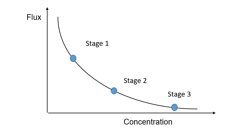
Figure 5 Flux Concentration
Setting up in the earlier testing phases a functional analysis, with one variable changed at a time will shorten a testing period establishing optimum operating conditions efficiently. The key variables are listed under the Key Objectives for the MSDS above and would be an early part of the testing protocol.
The level of membrane fouling by the process is of key concern to the MSDS and will often define the length of a test program. The protocol will need to create a baseline, usually water flux, for the brand new membrane and then monitor changes to the water flux over time. Critical for performance is not that the brand new water flux out of the factory is maintained but that the performance of the membrane stabilizes soon after first use.
Generation of a flux concentration curve is challenging for a continuous feed and bleed system where the pilot is not designed as an MSR system. In a three stage system for example, each stage will be operating at permanently at or around a single but different point on the flux/concentration curve (see Figure 5 Flux Concentration – MSR below). To get the flux, separation and fouling potential at that point, may require a single stage or batch pilot plant to operate for a time at that concentration, meaning that concentrate samples for the client are no longer available except when operating as the final stage.
Test Protocol
- Tests
- Clean water flux
- Membrane Selection
- MWCO
- Configurations tested
- Functional Analysis
- Pressure
- Temperature
- Cross Flow
- pH
- Concentration Tests
- Sample Protocol
- What needs analyzing
- What can be done in house
- How many samples needed
- Who pays
- Turnaround time – delays and there affect on testing progress
Passage of key compounds through the membrane must be understood. A membrane usually works on what is often called the SP or Salt Passage. This measures as a percentage the concentration of the compound on the permeate side of the membrane and the concentration on the feed side at the same time. The figure may be constant for any concentration of feed but often varies with pressure, temperature and feed concentration. This may create a need for analysis of a substantial number of samples at significant cost with the additional need to make sure that both the retentate and permeate samples are taken at the same time.
The testing program may be affected by the analytical timeline with delays in progress resulting from waiting for laboratory results to be returned.
Conclusion
The development of a membrane process will be most efficient and rewarding if the two parties work closely together to define objectives, establish a clear and encompassing test protocol, clearly define the roles of each party. Communication is key to ensure appropriate and necessary data is captured to allow the development process to move forward with informed decisions made each step of the way.
Risks should be properly planned for and the cost and time of testing reflect the risks being taken.
With a carefully planned and well executed program, the ultimate goal of having a well designed membrane system providing no operating surprises when first put into service will be met.
Keys to Success
- Communication
- Agreed documented goals
- Remember the budget
- Capture all the data needed to reflect the risk and meet the timelines
- Avoid analysis paralysis
- Assess the risk and plan for it
- Test protocol
- Regular reviews of progress